Thursday 30 June 2011

Multicolour 3D prints and 3mm filament joiner

I managed to get hold of some different coloured PLA, unfortunately I could only get 3mm filament, so after printing a new 3mm extruder which I can now also use to compare the Bowden setup with a direct feed, I decided to try some coloured and multicolour printing.
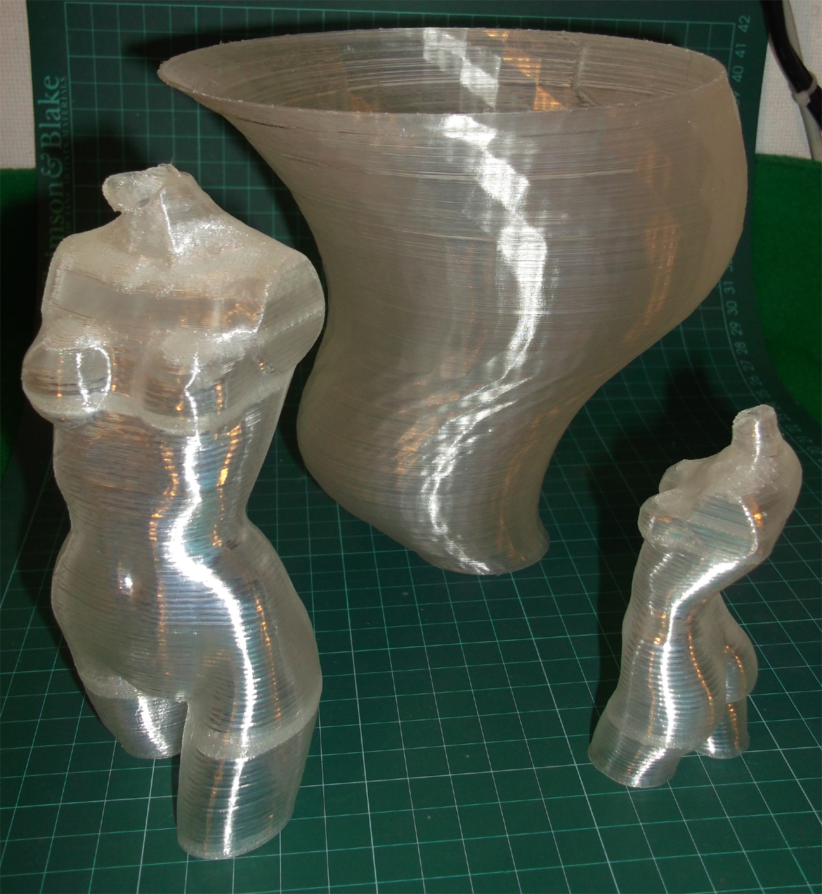
Here was the result of a few hours printing


Having printed these different coloured twisters I can see that each colour has slightly different properties.
It’s quite evident from the filament spanning in free air that you need different temperatures for each colour.


The Blue is particularly odd giving micro-bubbles inside the extruded filament if I run it at 196 deg c, but these are minimised at 187 degrees.
The Blue is also more brittle in it's filament form, but produces a very hard part when extruded.
The Red is also more 'sticky' and is a little prone to very fine strings, maybe a change in temperature will resolve this, I need to further experiment with red.

Black is lovely and glossy about 75% opaque but it's a smaller diameter than the others being an average of 2.7 so I needed to compensate in SF for this or my prints would end up less filled.


Yellow is my favourite for printing, its clean and precise when extruding at 196C, it layer bonds very well and the printed parts feel very similar to ABS, being strong but with a little give, it does not snap in filament form, just bends so softer than the blue but this is a good thing for printed parts being used for construction or use. I printed an extruder in yellow and it seems like the ideal  material if you are not using ABS. 
The Yellow also seems to have the best filament spanning properties, but I expect much of this is dependant on temperature and the 'softer' makeup of the material.

The properties of the Green filament fall between Yellow and Blue and looks really nice when printed, it seems to give the best definition of the printed object.

If you are interested in getting hold of different colour PLA then all the above colours were supplied by (Martijn Witte, martijn@net99.nl

Martijn is based in Europe and can do you a very good deal on PLA and ABS, contact him for more details and mention RichRap if you get a chance.
So after the different coloured objects I wanted to experiment with multicoloured printing -

People seem to do this in a number of different ways -
1) - Start the print with one colour filament, pause the print and reverse out the filament and load a new colour, continue the print.
2) - Join lengths of different coloured filament together and print them in one go (using hot-air guns or flames).
3) - Use multiple extruders with different coloured filament, produce some complicated Gcode to control them.
I tried joining with a flame (lighter) this is not a good idea, it does not work well and it's easy to snap the join after cooling, it also can char the filament, not something you want to feed into your extruder.
I then tried a flat heated block of Aluminium, melt both ends and join, roll them on the block, this works but can make a mess and it's a little fiddly.
And after a quick try of a hot-air gun (don't bother it's not easy at all) I decided to try and make a temperature controlled filament joiner - 
I decided to make a Aluminium block with a heated channel so I can join and rotate the filament, this works really well and it only takes 5 seconds to join pre-cut lengths together.
Cut an Aluminium block, drill a hole for the resistor (6.8Ohms) and then slice it so you have 'joining channels'

Bond in the resistor (fire cement)

Insulate it (spare PEEK block)

Wire it up and add a thermistor (I also added an LED to tell me when it's on)
Mount it to a block of wood or something you can clamp down.

You can use your RAMPS electronics setup and a host program to control the temperature as it's the same as your hot-end. (if you have a resistor hot-end that is)

I found a good temperature was about 160 Degrees C, this gives you time to heat and rotate the filament and also joins it really well.
So if you hold a piece of filament in each hand and melt both ends on the side of the Alu block, then sith the into the grove and push together then give them a quick rotate you should have a joined filament (after a little practice).

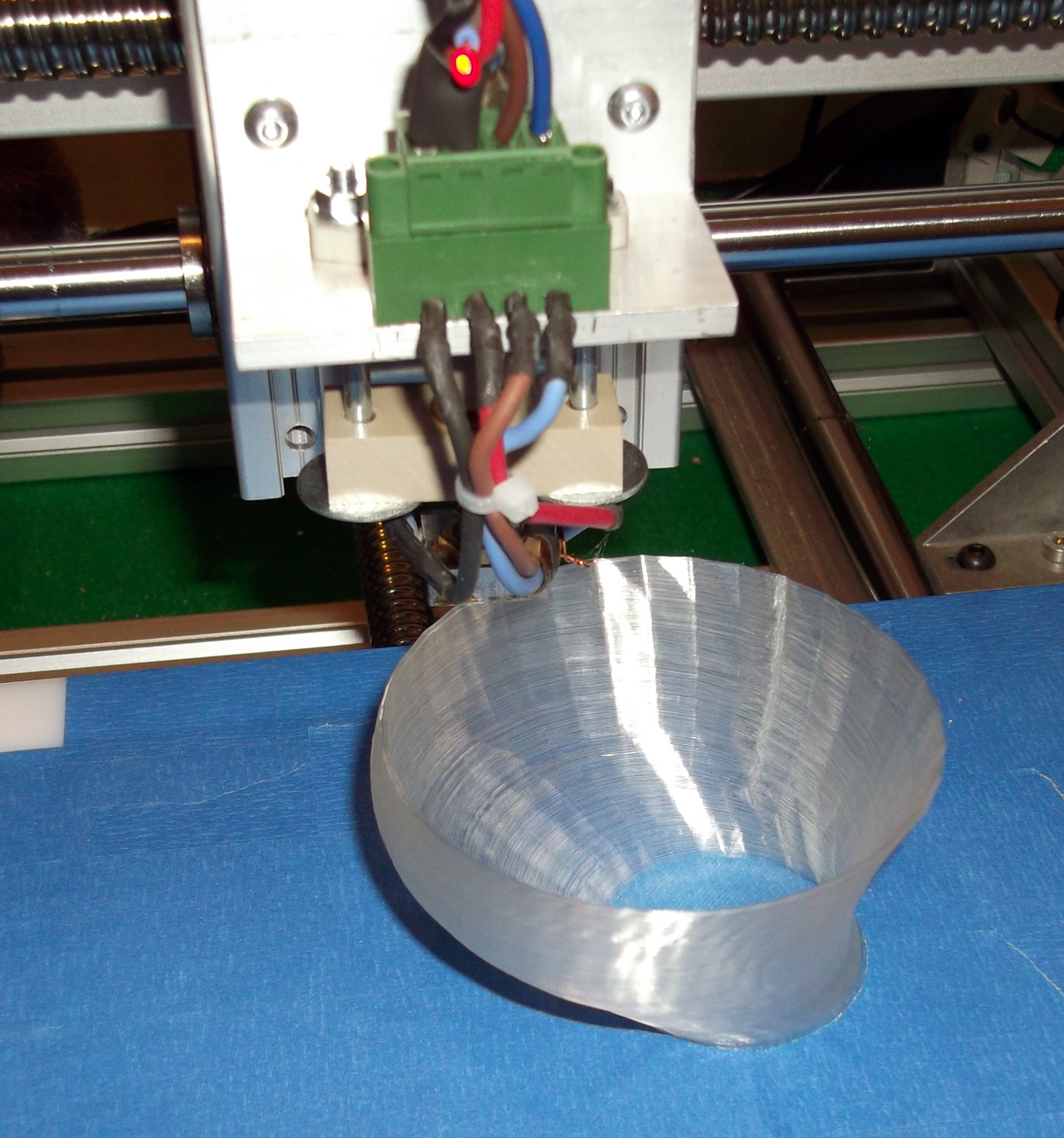
I join the multicoloured piece to the end of a roll so if your measurements over run the print will continue.

You can see above the blue is about to change to green.


I didn't know how the hobbed bolt would cope with the minor surface changes at the join, but it was not a problem at all, the filament just gets drawn straight down, I have not had a single problem.
So now I can print multicoloured things in one go.


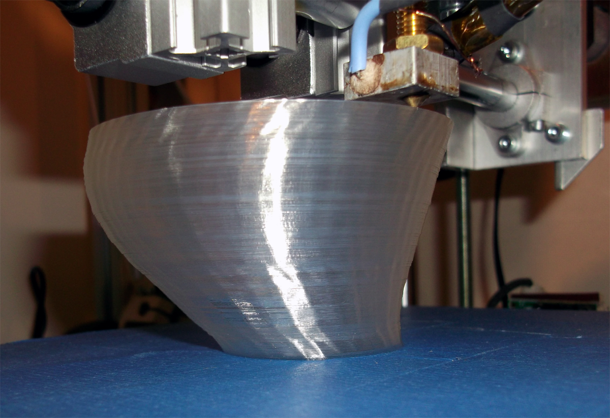
This coil of PLA printed the pot below

Tiger Stripes

Changes that I think would make the filament joiner better -
1) - Have a shorter heating zone, just ~4mm for each side, this would help keep the filament more rigid when you twist it to remove the join.
2) - Have a bigger flat area that you can quickly melt both the filament ends, I'm using the side of the block to do this, but a bit more area would be good.
3) - Have a cold block or wet sponge to rapidly cool the joined filament in place or a foot pedel (you need both hands to hold the two filaments) controlled fan so you can blast cool it.
*- Maybe make the heating block clamp together in two halves like an electric plumbing pipe joiner -  
If you had a foot-pedal controlled one of these for filament joining it may make the job easier.

Now the challenge was to be able to work out exactly how long each piece of filament should be so I could do whatever layer in whatever colour I wanted.
Thanks to a little advice on the reprap forum, Greg Frost pointed out that Grep could help me calculate the filament feedstock used per layer.
I needed this information for my next challenge... More soon on this.

Thanks for looking,

Rich.

Monday 27 June 2011

1st Replication and design improvement

Today I managed to make a clone of a clone on my 3D printer, something I have wanted to do for well over a year now.

It's not quite full Reprap machine replication, but a good start, and one that makes me smile :)

I decided to print out a Hinged Accessable Geared Wade extruder by  GregFrost


It's a really good design and printed out very nicely, check it out on Thingiverse, it's extruder design evolved to near perfection.
I printed a set of Heringbone gears to use on it, but I was so impressed with the way the 'normal' gears printed and worked, I decided to stick with them for now.

My wooden Bowden extruder printed the Clear PLA one and that just printed the yellow one with a small design improvement.


I wanted to see if running a direct extruder improved my prints over the Bowden setup, it is a slightly larger nozzle size and I'm experimenting with different coloured 3mm PLA at the moment so it's not a fair test quite yet. I'll let you judge if the prints are any better or not, I am now also running twice as fast so when I go back to my Bowden setup I'll need to speed that up also.


0.2mm Layer height, 2 outline shells, normal hinged idler


With this hot-end I have used just PTFE for the hot-cold transition zone, it stays cool-warm to the touch and no leaks so far.

Little tip for anyone putting wires on the tiny little thermistors - cover both legs in Kapton first, the crimp lower down and wrap each connection with more Kapton and then more Kapton around the whole lot.

 I found I was using a screwdriver to lever back the idler to remove and insert filament and generally clean out the hobbed bolt, so my minor improvement to Greg's design is shown below.

And this was the copy, with my own improvement to the idler, it has a built-in lever so you can pull it back to insert filament without undoing the sprung bolts.

I hacked it up in Sketchup, so if it is of any use to anyone else, maybe Greg or someone can make it an option in the OpenSCAD original?

This is also my first part from Sketchup - to- 3D printer, now I have that workflow going I'm going to design a few things...

That's all for now, thanks for reading.

Rich.

Edit -  I almost forgot that I had never toasted my printer, this seemed like a good point so I printed out a Shot glass and had a drink... and another... and anotttther... and nnatnother...........
And it water-tight !

Monday 20 June 2011

Hollow printing

Like many who print with natural PLA hollow objects start to look like good fun, they can be a little tricky to print but here are a few things I have printed so far and a few tips that worked for me -

I printed a few things with the 'Fill' module turned off in Skeinforge, this is ok, but you only get one (fragile) shell 'outline' and no base or lid on your model, for me this seems to be a problem with 0.25mm layers, the material seems to collapse on itself. So I experimented slowing down the print but really I wanted to have extra material both to make the hollow object stronger and help it stay up during a normal speed print. If you leave the 'fill' module enabled but set the infill density to 0 you get a hollow model and you can select multiple outlines and also get a nice base on your model, this seems to work really well if you are trying to print large things without a heated bed.

Here are some results printed at exactly the same speed I would print a solid model - (straight off the printer).


Firstly thanks to Sublime for the fixed model of the Pink Panther woman, here is the progress printing a 95mm high and a full height 150mm version -
Solid base on the legs gives it a really good grip on the bed.

Don't you love the way the light catches her............. curves.

That was the tallest thing I had printed until the twister below.

The full sized one is 600 layers @ 0.25mm each.

You can see from the edge that the visible banding is not a change in layer position and the object is almost completely smooth to the touch so the only thing I can think is that the slight change in heater temperature (bang-bang control) produces the banding effect? if anyone can confirm this or provide a better reason I would be interested in any feedback.
The camera also seems to extenuate it so something optical may also be going on.


The next object (twister) below was printed with two shells and a base, and full sized it's quite big.
I expect that I could have made it single walled if I slowed down the speed, but I would rather have a stronger object for the same print time.


This is the very Awesome Ultimaker Twister by Martijn


I have about 140mm more on my Z axis, so maybe I need to print something really tall next time.

I'm almost certain this is completely watertight, and as it has a sealed bottom of 3 layers I could use it as a vase.

Thanks for looking, and if you try printing hollow things let me know how they turn out for you.

Rich.

**************** EDIT ************ UPDATE ********** 27th June ***************

Thanks to Sublime for working out why Skeinforge still adds infill even with a hollow print causing the banding of infilled areas seen above in my prints - 
So you need to turn off 'Infill in direction of bridge' in the Carve tab of Skeinforge for some models if you want a nice clean hollow print, but make sure you have your extruding temperature correct for the filament you are using, as you will suffer bridging issues if it's not spot-on, without this 'infill-support' you will be spanning free space.


When you slice this is what you may see with 'Infill in direction of bridge' enabled or disabled - 
Skeinforge sees extreme over-hangs in the model which forces it to create the infill.

'Infill in direction of bridge' in the Carve tab of Skeinforge 'ENABLED'

'Infill in direction of bridge' in the Carve tab of Skeinforge 'DISABLED'


**************** EDIT ************ UPDATE ********** 27th June ***************

Thanks again Sublime, I'll try a few more hollow things now.

Rich.

Thursday 9 June 2011

Skeinforge Version 41

I have been using Skeinforge for just over 1 week now and I'm starting to get a grip on this most fantastic program.
After initial machine setup and printing with Reprap Java Host I always wanted to move over to Skeinforge, but it has a bewildering array of settings and control, quite daunting when you first start.
- But well worth the effort - 

This image shows my best possible print quality I managed from Java Host to generate Gcode (on the left) and one of my very first Skeinforge prints with initial 'good' settings, and it's still getting better and better all the time I learn more about Skeinforge.


Some excelent information and advice from long-term Skeinforge users for the new Version 40/41 can be found on the Reprap forum here - http://forums.reprap.org/read.php?154,75635
And also on the Mendel-parts forum here - http://www.mendel-parts.com/new_forum/phpBB3/viewtopic.php?f=37&t=256

Many thanks to everyone as I would have wasted a lot of time if not for this head-start.


The Skeinforge manual and settings descriptions are also found here - http://fabmetheus.crsndoo.com/wiki/index.php/Skeinforge


My setup is not typical of a Mendel or other Reprap, so your exact settings will be different, but the following information, notes and advice may help you get going if you are new to Skeinforge and are not sure where to start.

One of the first problems I had was the fact I didn't know how well my machine would print so it was quite hard to judge when I actually had it calibrated to a good standard.
Other than looking at other people's prints on thingiverse it's hard to say how good your machine should be?

First Step - Measuring E-steps/mm for the new Dimension changes in V40/41

I'm using a Bowden extruder setup that has some extra issues ascociated with controling filament hysterisis but the following is required for any extruder in any configuration.
My extruder being belt driven is also different from a Wades or Adrian's geared version, but in principle operates in the same manner, but with different gear ratio etc.

I setup my Extruder on a stepper motor test jig I had made to test Pololu modules, it's just providing a simple button to full-step the stepper motor.

I'm using 1.75mm Feedstock and now Dimension requires you to set 1mm of INPUT feedstock. 
Before the firmware required 1mm of Extruder Feedstock, this is an important change and makes a big difference for making nozzle size changes easy and generally everything else easier.

I marked the filament with tape on the extruder output and then counted how many full-steps (button presses) were needed to extrude 10mm of feedstock.
I did this again in the reverse direction to make sure of my count. Take as accurate measurement as you can for this.

10mm of driven feedstock = 348 full steps
I am really running my Extruder at 4 x microstepping, so 348 x 4 = 1536

And in the Firmware you need to provide a value for 1mm of feedstock so that would be 1536/10 = 153.6
So I used 153, recompile and download.

Then you need to accuratly measure your feedstock, I measured with a digital micrometer 10 random section of the coil and the average was 1.792mm

These settings need to be entered into the 'Dimension' tab in Skeinforge.


Many of the sections in Skeinforge do not need messing with, the ones you will need to play around with are 'speed' 'raft' and 'fill'

After setting your input filament perameters Feed and Flow under 'speed' are the most infulentual settings to play with along with 'infill width over thickness (ratio) in 'fill'


The next bit of advice is to make your machine Go Slow for initial test and calibration of flow/feed, I wasted quite a lot of time trying to run my machine too fast before I had these settings correct, you can easily speed it back up afterwards.
So set the 'speed' for the machine to 20 or 30mm / sec

Set your flow/fill speed -


Set the extruder speed Feed and Flow the same value, I started at 16mm/sec and went up and down from there.

This picture shows the effect of Flow/Fill on my machine (0.25 layer height) 160 layer 40mm tall 10mm cube.

I decided to turn off 'Limit' as I have acceleration in my Firmware, but you may want to enable it to help protect your machine from over-speeding especially on the Z axis.

If you are not using a heated bed (or even if you are) you may want to make the first layer go slower than the rest to help it stick to the bed.
Raft can do this, although you don;t actually need to make a raft just use it for slowing down the first build layer outline and initial fill.
See the Above links to Reprap forum and Mendel-parts for more on this and all the other sections.


Then tune your solid fill rate - 
Some of the guides talk about setting 'infill width over thickness (ratio)' to 1.7 from the standard default of 1.5. I found that my solid layers had too little plastic at 1.7 and 1.5 so my setting is 1.4, this gives me a perfectly filled solid layer without any 'spare' plastic, if your nozzle is pushing about plastic on subsequent layers of a solid fill (object base) then raise this number. if it's too sparce and you have tiny gaps between filament make this number smaller.

This solid base was with it set to 1.5, I settled on 1.4 in the end.

These are the different tool-paths for 1.0, 1.5 and 1.7 infill width over thickness (ratio) settings

Correct Filament Reversal length -
* Very important with a Bowden extruder *

I did get lucky with my first guess at required Filament reversal length, but the above image show the effect of not having enough reversal (lots of strings)
On the left is a 1mm reversal, middle is 2mm and printing on the right is a 3mm filament reversal. I may be able to get away with 2.5, but for now I'll stick to 3mm.


It's easy to fool yourself into thinking you have ok settings using a standard test cube, I have found that this model (below) is an excelent peice for machine calibration and it's quick to print so you can try out settings quickly.
It's a hollow pyramid by (3dprinterbot) found on Thingiverse -.http://www.thingiverse.com/thing:8757


This was still early on in the Skeinforge tweaking, but even so a great improvement over Java host.

No Strings !
Java host generated on the left, and Skeinforge V41 on the right. (With strings, but in the right places)

This was my most recent print, with super-refined settings. 
This proved to be a good test of filament spanning, you can see the solid layers at the top, under this is hollow, and then a solid base at the print bed.
I stopped the print as I have hit a problem with Gcode generation on Hollow objects. 
I'm going to need some help on sorting that.

Anyone like to guess on what this object is? 
When I get it all printed out you can see if you were correct.

If you are new to Skeinforge, I hope that some of this may help you or at least show you that it's worth learning how to use it.

Thanks for reading.

Rich.